Week 2 - Proximity Sensor Research
Jisoo, Seeha, Jaye, and I worked together researching and experimenting with a LiDAR sensor. LiDAR stands for: LiDAR, an acronym for "light detection and ranging,". Simply the sensor fires a laser from a transmitter and the sensor tracks how long it take until it hits an object and returns to the sensor's transciever. Unlike other types of proximity sensor
How LIDAR Works
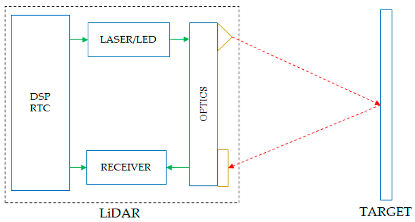
The LIDAR sensor works similarly to many other distance or proximity sensors like a PIR or Ultrasonis sensor. A LIDAR sensor first shoots a laser from one optical lens with a 905nm wavelength (invisible to the human eye). A receiver in the sensor waits for the laser to bounce off an object and return to the sensor. The time it takes the laser to return is used to calculate how far away an object it. Unlike other proximity sensors available to research LIDAR sensors have a long range and are used in a lot of application when the sensing takes place over large distances.
Common use cases for LiDAR technology:
- Autonomus Vehicles object detection (ex: Waymo cars)
- Environmental Monitoring
- Aerial scanning (ex: topographic mapping and elevation modeling)
Generally any long-distance use case of spatial mapping can use LiDAR technology.
Setting Up the Sensor
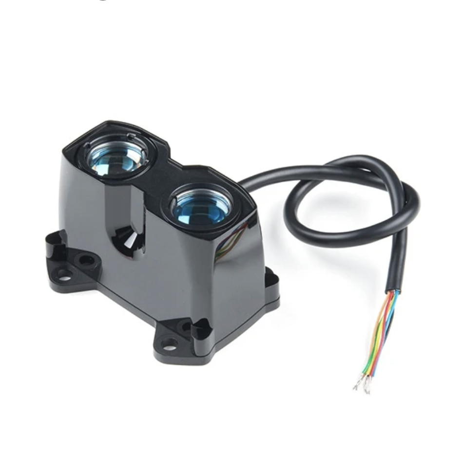
For the project, we were testing the Garmin LIDAR-lite V3HP. Below is a short description found on Sparkfun's product page for the sensor:
The LIDAR-Lite v3HP is a compact, high-performance optical distance measurement LIDAR sensor from Garmin™. It represents the next generation of optical ranging, building on the popular LIDAR-Lite v3 by enhancing performance, improving power efficiency, and incorporating a rugged, IPX7-rated housing. It is the ideal, cost-effective ranging solution for drones, robots, and unmanned vehicles (UAV/UGV) applications.
Sensing Range: 1m - 40m
Though testing showed the sensor can read as close as 5cm On the floor, sensor became less accurate after 20m General accuracy is +/- 2.5cm
Testing the sensor
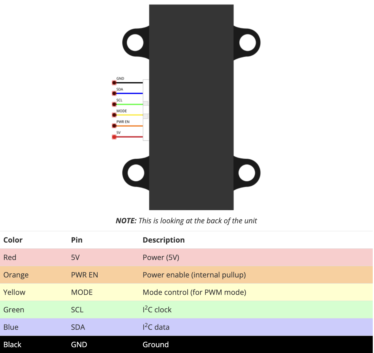
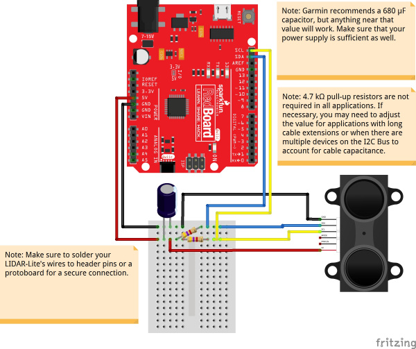
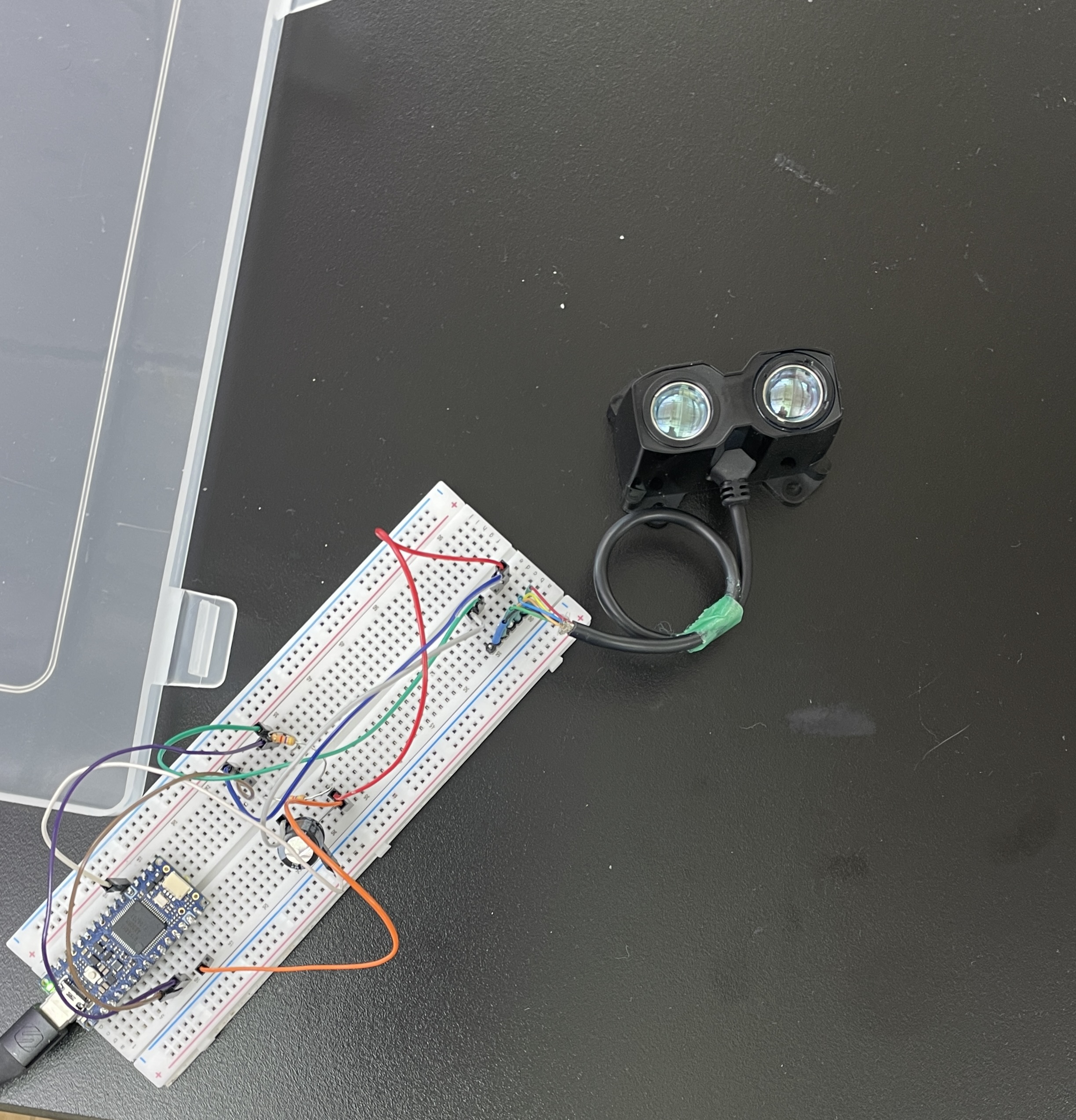
The sensor itself was easier to set up than expected. To observe general distance from the sensor, the Mode and PWR EN wires could be ignored. The rest of the system could be set up as a simple I2C connection communicating with an Arduiono through the SDA and SCL pins. In the system, the two I2C connections use a pull-up resistor to ensure adequate current flow. The sensor is powered by a minimum 680uf capacitor by 5V DC power.
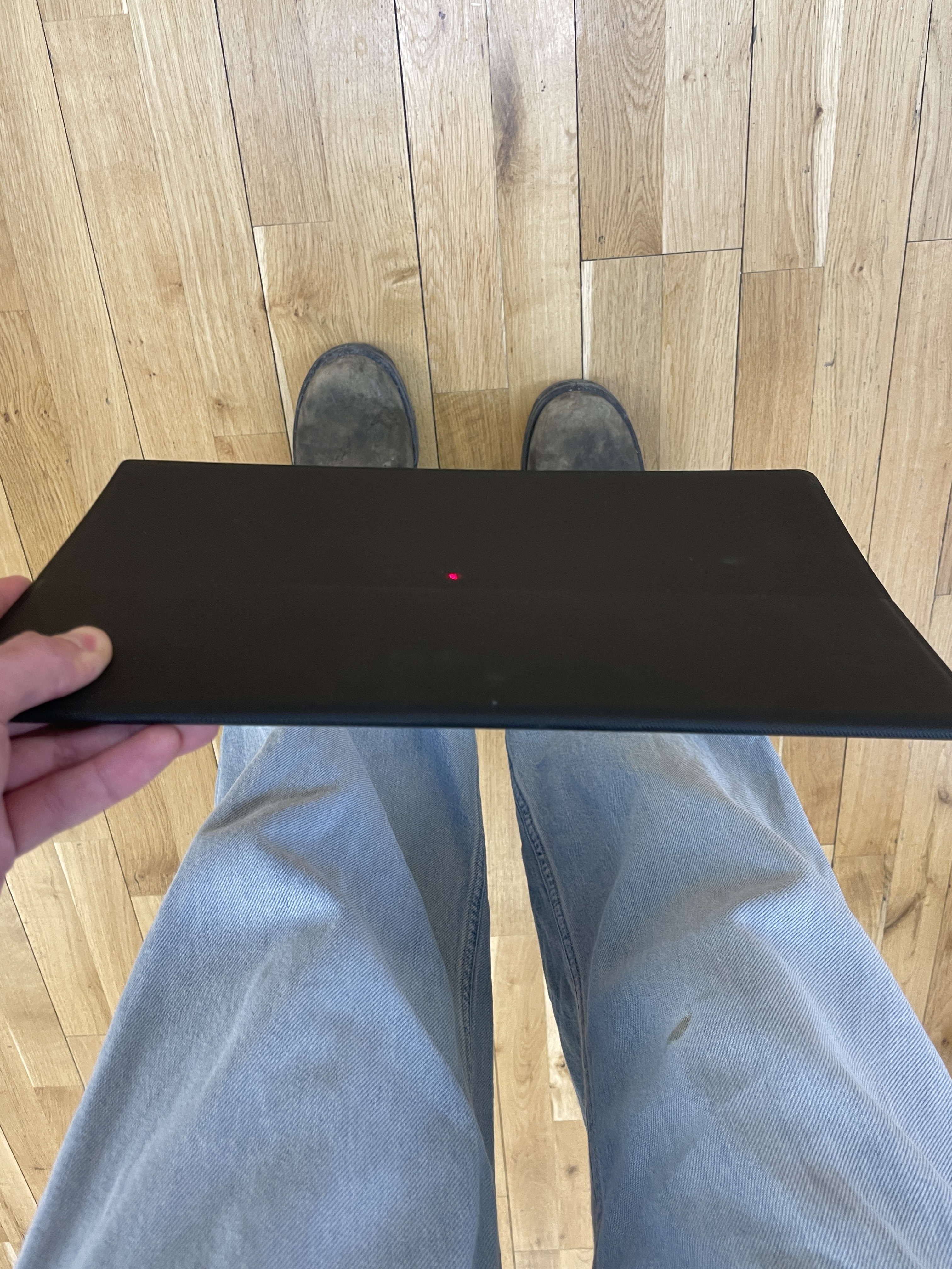
We placed the system and laptop on a chair to see what maximum distance could be read by the sensor on the Floor. To make sure an object was in line with the sensor we used a laser pointer on top of the LiDAR sensor. We found the sensor could accurately sense about 20m of ditance before the value being read by the Adriuno became inconsistent. The inconsistencies in distance could have been from a variety of factors such as reflectivness of the object being sensed. In larger applications, weather plays a large role in the accuracy of LiDAR systems too.

To program the Arduino, a library was needed to accruately convert the information being received by the sensor into distance. We used the example code provided by Sparkfun's hookup guide for the sensor:
                        /**
                        * LIDARLite I2C Example
                        * Author: Garmin
                        * Modified by: Shawn Hymel (SparkFun Electronics)
                        * Date: June 29, 2017
                        *
                        * Read distance from LIDAR-Lite v3 over I2C
                        *
                        * See the Operation Manual for wiring diagrams and more information:
                        * http://static.garmin.com/pumac/LIDAR_Lite_v3_Operation_Manual_and_Technical_Specifications.pdf
                        */

                        #include
                        #include

                        // Globals
                        LIDARLite lidarLite;
                        int cal_cnt = 0;

                        void setup() {
                            Serial.begin(9600); // Initialize serial connection to display distance readings

                            lidarLite.begin(0, true); // Set configuration to default and I2C to 400 kHz
                            lidarLite.configure(0); // Change this number to try out alternate configurations
                        }

                        void loop() {
                            int dist;

                            // At the beginning of every 100 readings,
                            // take a measurement with receiver bias correction
                            if ( cal_cnt == 0 ) {
                                dist = lidarLite.distance();      // With bias correction
                            } else {
                                dist = lidarLite.distance(false); // Without bias correction
                            }

                            // Increment reading counter
                            cal_cnt++;
                            cal_cnt = cal_cnt % 100;

                            // Display distance
                            Serial.print(dist);
                            Serial.println(" cm");

                            delay(10);
                        }