Week 3 - Analog Output
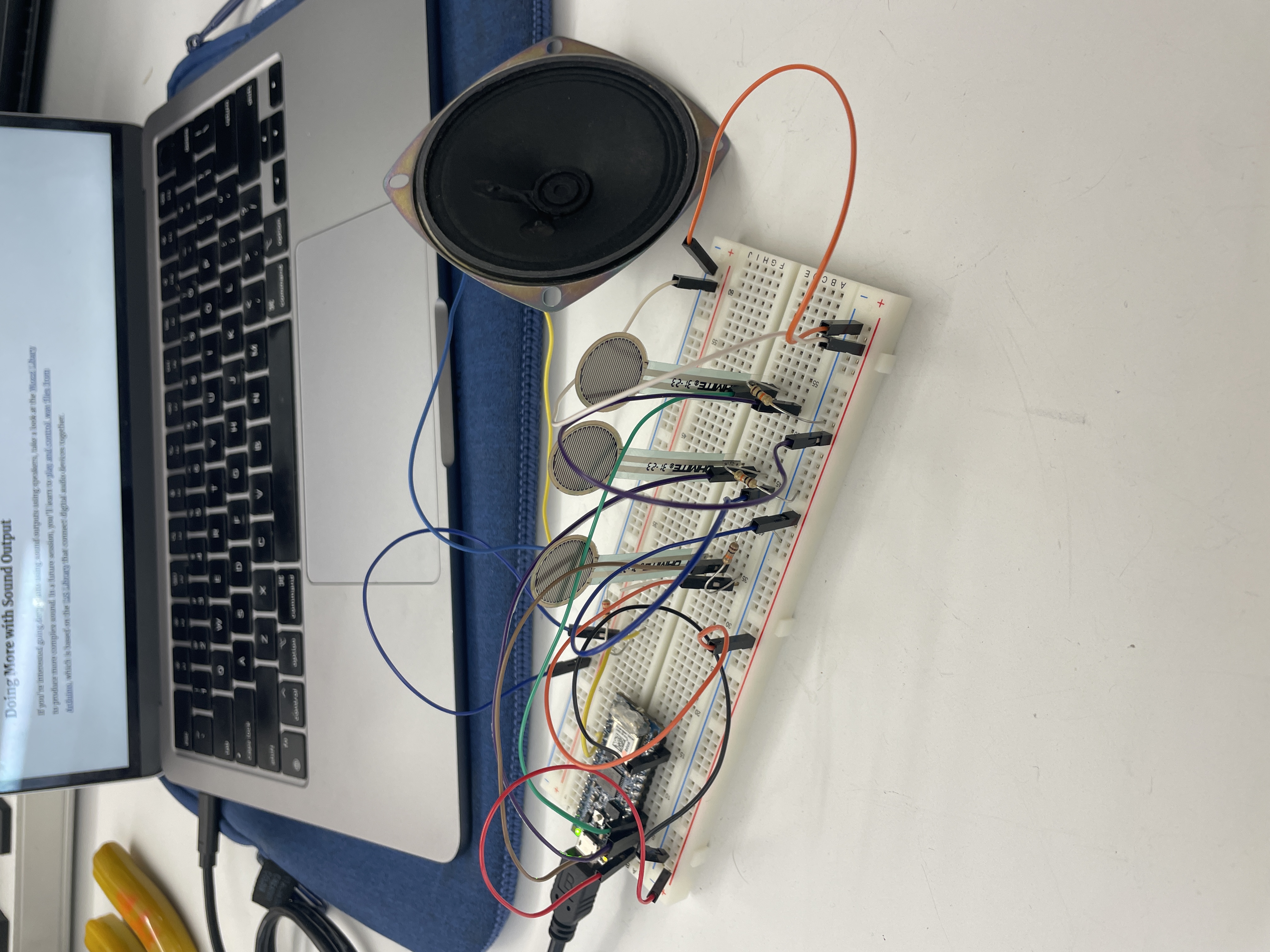
This week's lab helped inspire me with potential ideas for future projects. Implementing the analog tone speaker and servo was quite fun and straightforward. I managed to get away with bending some stripped wires around the speaker connections instead of soldering it to save time on the labs. Last week's class helped solidify the differences between digital and analog pins, and the relationship between the Arduino code and the hardware it operates.
                        #include "pitches.h"

                        const int threshold = 10;      // minimum reading of the sensors that generates a note
                        const int speakerPin = 2;      // pin number for the speaker
                        const int noteDuration = 20;   // play notes for 20 ms

                        // notes to play, corresponding to the 3 sensors:
                        int notes[] = {
                        NOTE_D8, NOTE_B4,NOTE_B3
                        };

                        void setup() { }

                        void loop() {
                            for (int thisSensor = 0; thisSensor < 3; thisSensor++) {
                                // get a sensor reading:
                                int sensorReading = analogRead(thisSensor);

                                // if the sensor is pressed hard enough:
                                if (sensorReading > threshold) {
                                    Serial.print(sensorReading);
                                    Serial.print(" ");
                                    Serial.print(notes[thisSensor]);
                                    Serial.println();
                                    // play the note corresponding to this sensor:
                                    tone(speakerPin, notes[thisSensor], noteDuration);
                                }
                            }
                        }
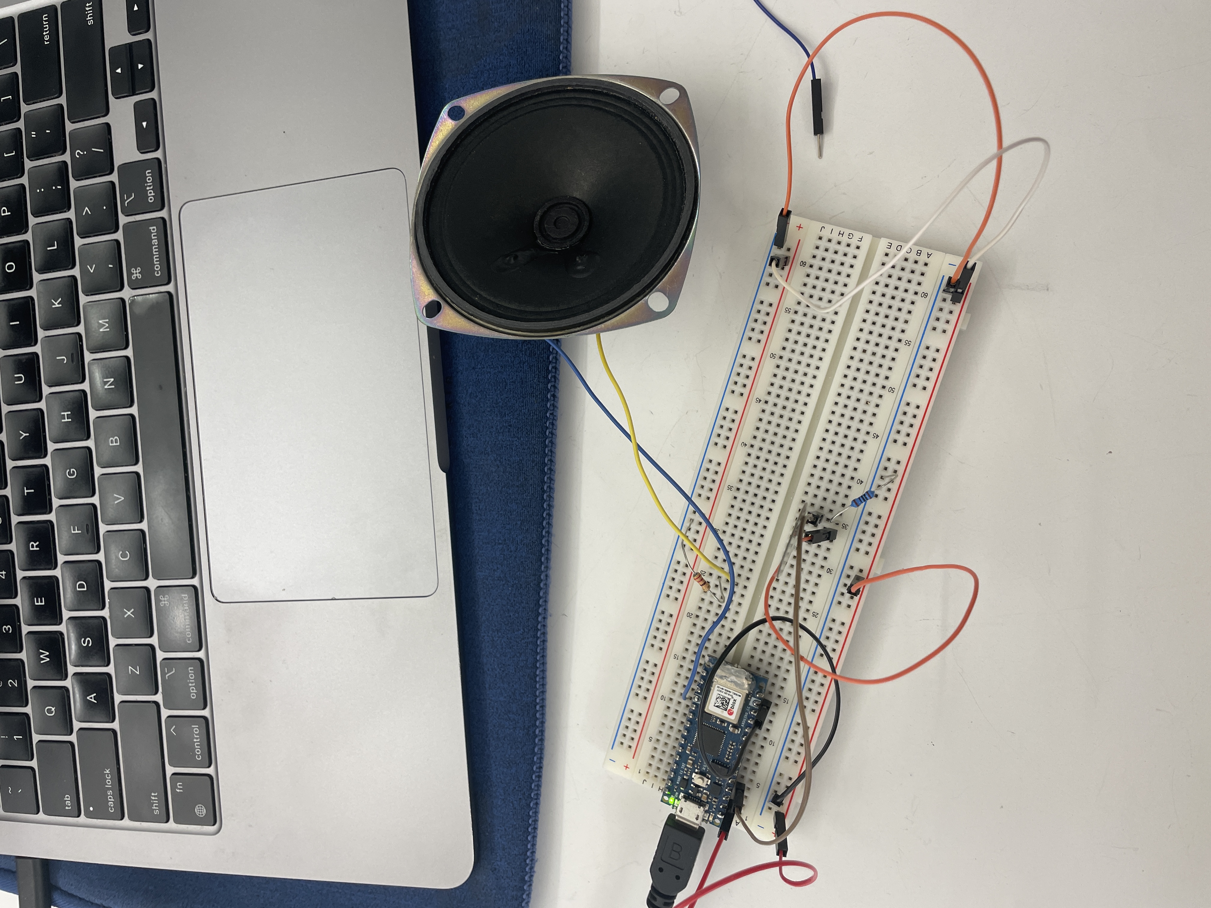
While I was able to correctly set up the speaker lab, I ran into trouble when I attempted to increase the speaker's power and volume. I added a 10V capacitor to my circuit and a ~4000 Ohm resistor (calculated using Ohm's Law) but after using a multi-meter, the circuit still read 3V and the speaker sounded just about the same.
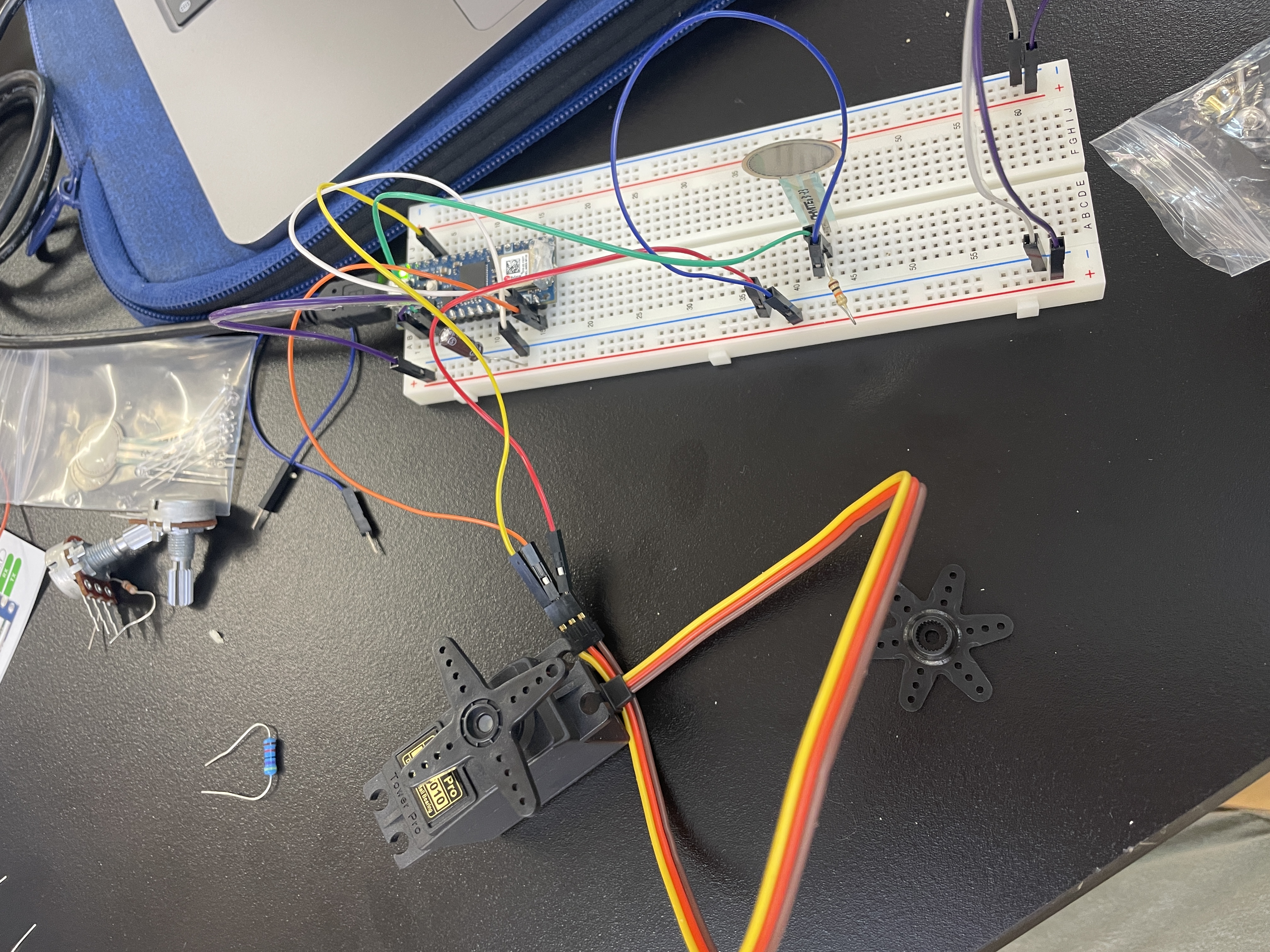
Meanwhile, the servo helped show me new ways I can create movement in future physical computing systems. The rotation of the servo didn't seem like much though I know it has a lot of possiblities especially when an analog output is used on different types of motors. My next goal will be to try and find time to experiment with creating more complex circuits.